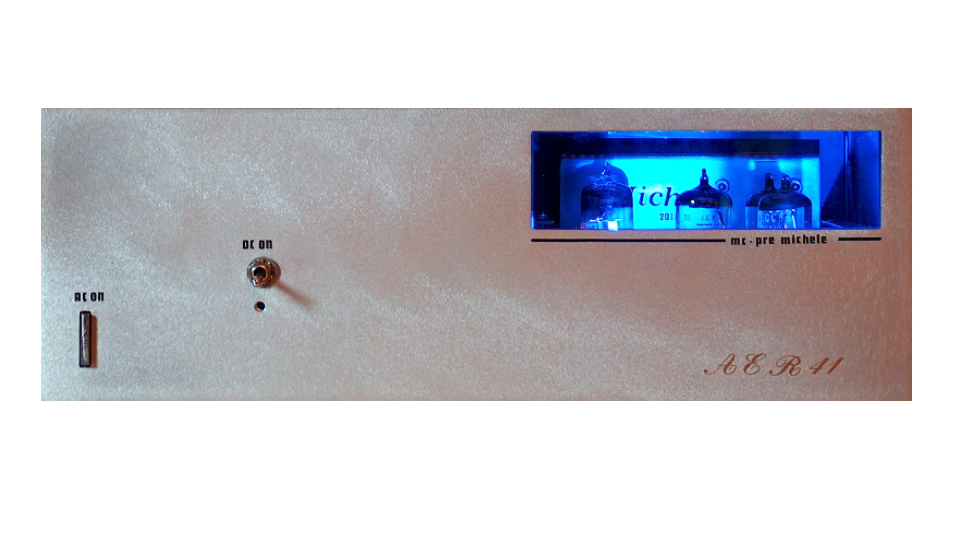
MC Pre Michele : Battery operated Vacuum tube
MC pre-amplifier.
More than anything else, the idea of building a battery operated MC pre, was to verify the advantage of such supply in respect to a classical AC operating power source.
One of the condition, however, to make thi possible was to find and use a low plate voltage tube to avoid excessive series of batteries. For this purpose a suitable valve is the ECC86; specifically designed for Hi frequency amplifier it performes as well in audio frequency applications.
Its main characteristics are:
- Va 25V
- Ia 20 mA max
- Vf 6.3
- V 0,3A
- µ 14
The specification of this pre were established as follows:
a) Vacuum tube technology with the exception of the Moving Coil (MC) input stage
b) Zero feedback
c) Passive RIAA equalization
d) 48 Vcc max dc voltage
e) Hi End class
The blocks diagram can be seen in Fig. 1 where only one channel is shown. A high gain input stage provides a 56 db gain required for low level MC cartridges (200 -500µVolt. This stage must have also a high signal to noise rate in order to minimize hum and hiss at the output.
Its output feed a passive RIAA equalization network. RIAA has a negative gain of 20 db at 1Khz which are restored by the following buffer circuit which, in turn feeds, thru a DC coupling, a cathode follower to allow remote connection to a line amplifier.
This pre does not have a volume control as it is intended to input a line amplifier which usually has its own regulation.
The power supplies section is made up of voltage regulated circuits both for heater and plate voltages.
The diagram at the bottom of Fig. 1 shows graphically the gain/loss of various stages.
The construction of this pre-amplifier requires a good knowledge of audio frequency electronics, assembly techniques and high sensitivity circuit inherent problems. This preamp is not for inexperienced DIYers; whoever approaches its construction must be aware of this, otherwise He or She will end up with an unsatisfactory product. This difficulties, however, are very challenging.
When this pre is fed thru an Ac outlet, relay RY is energized and feeds all circuits by means of internal power supplies. AC/DC switch does not have any effect.
If mains is turned off and AC/DC sw set to DC, the preamplifier is fully fed by the DC voltages supplied by the external rechargeable batteries. 12V/1,3 Ah x 4 = 48 Vcc for plate voltages, plus 6 V/12Ah for heaters).
Design concept
Having established a set of requirements (“a” through “e” above) it appears immediately clear that a conventional cascade of triodes circuit cannot stand this demand. Distortion below 1% can hardly be achieved unless several db of feedback are applied to the circuit.
This conflicts with requirement “b” and “e” where zero feedback and High End requirements are the design goals.
Additionally, a high performance circuit must be “fast” (high slew rate) and presents a wide bandwidth in order to provide good response to the transients.
To achieve these design requirements a survey of alternative circuits became necessary and ultimately lead me to focus on the SRPP (Shunt Regulated Push Pull) configuration, better known as totem pole.
It has been largely used, in the past, in instrumentation and professional fields, as high frequency line driver and voltage amplifier.
Its operation has been described in several magazines however an exhaustive description can be also seen at:
>>> (www.tubecad.com/may2000/page2.html)
Finally, as stated earlier, in order to operate with low plate voltage a suitable valve must be selected. Among limited alternatives, the ECC 86 represents a good choice as it is still available at a reasonable price.
The totem pole circuit, with the appropriate components values, provides a gain of 20 db (10 times) with a distortion of the order of <0,1% at 1Volt output without application of a feedback loop, a high slew rate in the range of 100V/µsec and a bandwidth reaching a MHz.
Low level signals, such as those coming from the MC cartridges, are in the range of 200-500µV at 1 kHz or less and require an amplification factor of 1000 times (60 db) to reach at least 200-500 mV output level needed to drive a line amplifier.
A vacuum tubes circuit can hardly stand up to these requirements considering also the intrinsic noise problem introduced by them.
A brilliant solution has been identified by the designer Aloia and, as He claims, this was never done before (Fig 2 V1 e TR1).
He gave this circuit the name of TOPOHYBODE; an acronym of TOtem POle HYBrid cascODE.
It consists of a totem pole in a cascode configuration with a NPN low noise transistor.
The performance of this circuit is outstanding: it exploits all advantages of the vacuum tube and the transistor, with its simplicity and over 30 db overload capability, it surpasses by far any other solution.
Finally, a passive RIAA equalization network completes the hard part of this circuit.
Design implementation. (Fig 3 wiring diagram)
Low level inputs stages require to be rather quite in order to maximize the signal to noise ratio necessary for good performance.
All possible technical arrangements have been implemented into the design to reach this goal.
This has been achieved by selecting a quiet tube such as the ECC86/6GM8.
In addition all the tube heaters are fed using a direct current while the plate voltages are supplied by a dedicated voltage regulator to stabilize its output and remove any possible ripple. Circuit has the option to be fed by external rechargeable batteries for additional noise reduction and overall quieter circuits..
The power supplies schematics is shown in Fig 4.
While the Hi voltage (+48Vcc) power supply is provided by a simple voltage regulator, the 6 Vcc is made up by a LM 338K, three terminals integrated circuit. Both circuits output can be adjusted by means of a dedicated potentiometer.
Battery supplies are activated when mains is off and SW 2 is turned on. Diode 1N4007 on TB3-3 prevents an accident polarity reversal of 48 Vcc external battery to protect all electrolytic caps. Polarity reversal of 6 Vcc battery does not have any adverse effect.
The MC input can be loaded with a selected resistor to better suite Cartridges specifications. A dip swith allows selection of load values from 12 Ohm thru 1K in 15 steps.
V1 output, feeds a passive RIAA network made up of R1, R2, C1,C2. The signal is then applied to V3, V4 buffer stage for an additional 20 db amplification.
V5 functions as cathode follower to provide the lowest possible output impedance; it has no gain.
My implementation, uses a high grade power transformer. Pre is quieter when fed by batteries, but in a normal listening environment the use of transformer does not deteriorate sound quality.
Lastly, great care must be taken on the grounding scheme by separating signal ground from the power ground wires.
The detailed schematic shows how this has to be done.
Adjustments and check out
The power supply should be checked out before making any connection to the pre-amplifier sections to make sure all voltages are correct.
It would be good idea to test it by loading each output as follows: 6Vcc heater PSs with 4 Ohm each (1,5 Amp), then adjust 680 Ohm trimmer for 6 V output; 48 Vcc with 10 kOhms by adjusting 20Kohm Potentiometer for proper voltage.
T1 bias adjustments has to be carried out as follows: with no input signal, measure collector voltage and adjust base potentiometer to read 1,3 – 1,35V.
Conclusion
Certainly, the use of batteries eliminates completely any hum from the preamplifier. However, with an audio-grade transformer, and great care in the grounding system, you can reach an acceptable level of hum which in practice it disappears (masked) when a record is played at any volume level.
A.E. R. Tambre – Italy
Yes Positive.