Matteo*, a new born,
10 watts integrated
stereo amplifier

Preface
I’d like to give credit to the AudioXpress <<www.audioxpress.com>>, a US magazine where my article has been hosted on their august 2007 issue. (Fig. 0)
Matteo* a 10 W vacuum tube Amp
The idea to build a low power, high quality power amp came after I had built the small French towers (AudioXpress March 2005 issue). These two little towers were so good in relation to their cost, dimension and look, that they deserved to be driven by a dedicated Hi-Fi amp.
But, what scheme? Which technology? The answer came rather quickly: A classic 1950’s schematic with modern modifications, where justified, and of course, vacuum tube tech.
The choice
I have reviewed several designs with different output power and features but I elected to start, as a base, with the one described in the reprint of “RCA receiving tube manual” page 692 (a push-pull capable of 15 Watt .From that base I made the following, substantial modifications:
- Employment of EL84s as power tube in an ultralinear/reduced load mode, instead of 6973s. (lower cost and readily available)
- No more than 8 –10 watts crisp and clean.
- A “no compromise” solid state power supply.
- Addition of a passive tone control circuit.
- Selections of inputs, through relays as opposed to a rotary switch.
- Addition of a power indicator meter (just for fun and to give it an esoteric look)
The schematic
The final version of the schematic can be seen in Fig. 1. The input stage is a V1 Cathode Follower (C.F.) with no gain. It is physically located close to the input relays board, on the back of the chassis; it transfers selected signal to the treble and bass controls located at the front panel.
This arrangement allow the signal to travel across the whole amplifier in a low impedance line, reducing potential hum pick-up and high frequency loss. In addition, the C.F. allows to feed the rec-out sockets without significant load to the circuit.
The inputs selection arrangement uses a 4 positions pushbutton switch to drive the proper relay.
Selected Input is loaded by the value of RL, which I elected to be 100Kohm.
From the tone controls, the signal goes to a V2 amplifier stage, which is necessary to restore the loss of the tone control circuits itself.
These two stages, including attenuation introduced by the tone controls, have an overall gain of about 2,5.
The driver stage is a pentode/triode V3, 7199 and provides proper amplification and phase inversion to drive the push-pull stage with an undistorted 22 Vpp signal. A 100Kohm pot with a 10K loudness tap provides the volume control. The loudness can be inserted by means of a push button switch which, in turn, activates a relay.
The cathode of 7199 pentode section receives a 15 db negative feed back from the output transformer secondary winding. The amplifier has shown to be very very stable without adding a capacitor in parallel to R19.
A considerable variation (with respect to RCA manual schematic) was done in the final stage.
The concept of this modification (as described in the 1959 Philips manual) is based on the fact that average signal value of music and speech is considerably lower than max output signal measured with a constant sine-wave; therefore when the output stage is polarized via a high cathode resistor bypassed by a capacitor, the bias voltage remain relatively constant even if the signal peaks to its max level, thus, emulating a fixed grid bias condition. The advantage of this solution however, is that the cathode polarization produces a lower distortion with respect to a fixed bias scheme as seen in the table 1, when the stage is driven toward high power level by peak of music or speech signals.
The stage employs a push pull of EL84 with a 440 ohm R24, R25, ½ P4 cathode resistors (390 + 50) per tube bypassed by a 100mF capacitor, This solution allows the tubes to work with a reduced load. The EL84 total idle current is in fact 25/27 Ma per tube instead of an usual 40 Ma, dissipating 30% less power and increasing tube’s life considerably. The disadvantage however (a theoretical disadvantage) is that the stage cannot be driven to full power using a continuous sine wave signal: the distortion will be excessive since it is designed to handle peaks of power.
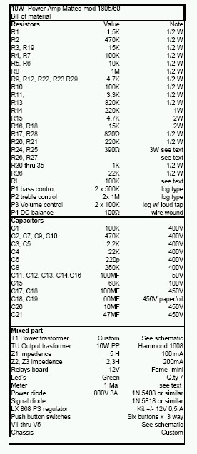
The bill of material is listed in the related table (to print the bill of material click here to open .pdf file)
Table 1
|
Distortion measurements under different bias conditions
|
||||||
|
Output power (W. peak) 2
|
2
|
4
|
5
|
8
|
10
|
12
|
|
Fixed Bias Condition. Distortion
|
0,4
|
0,9
|
1,4
|
2,0
|
2,6
|
3,4
|
|
Cathode bias (reduced load). Distortion
|
0,4
|
0,9
|
1,1
|
1,2
|
1,3
|
1,4
|
A 100 Ohm pot, on the cathode circuit, allow for a DC balance of EL84 tubes.
Should you desire to establish standard operating conditions, replace the R24 – 25, 390 ohm resistors with 2 x 220 ohm. You may elect to leave the bypass cap or take them off to add some sort of feedback.
From the 16 ohm tap, the signal thru R26, R27, feeds a meter to monitor the output power. The resistors value is chosen to obtain a full scale reading at max output.
Power supply
As stated earlier, the power supply Photo 3 is a no compromise circuit with CLC filters all over. There is absolutely no hum at the speakers even if you put your ear inside them.
The power stages get their voltage through two separate CLC cells (Z2, Z3), while the input stage and driver sections get their power through a third CLC cell (Z1).
A +/- 12 volts fixed regulator feeds the heater of first two stages and the various LED’s used to backlight the pushbutton switches.
There appear to be a lot of redundancy in this circuit, and in fact there is; however it is there to give no excuse to the final stage to become short of current when He needs it.
Assembly
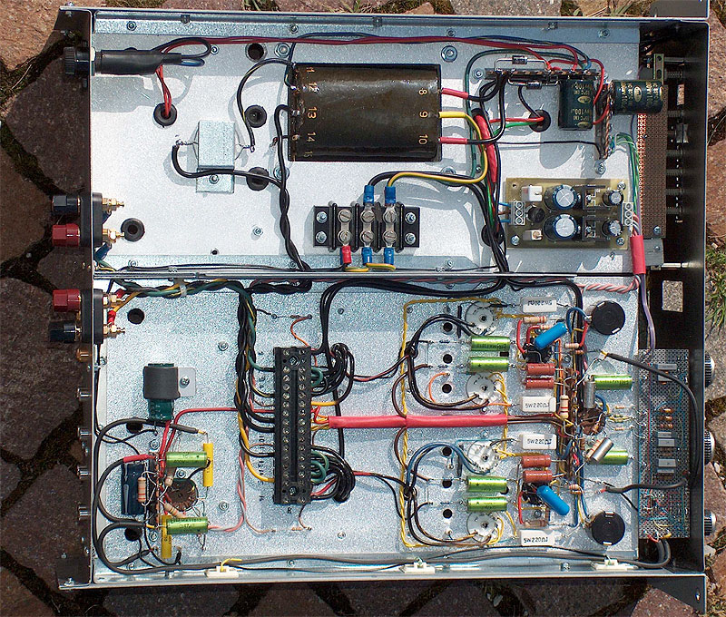
The whole amp is built with point to point wiring with the exception of relays input board and 12 volt cc filament supply which were made from commercial kits. Photo4 and 5 show the component layout and all the related wiring. Even if this is to be considered a small and relatively simple power amp, it must be built with great care. Good components throughout are essential to achieve quality results.
Mechanic and controls
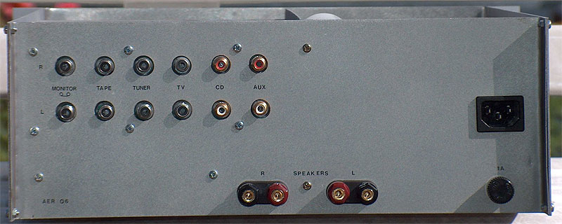
The chassis is an old Wavetek Sweep-Marker no longer in use, modified as required to fit the new mechanics. The front panel accommodates the tones and volume controls, a push button input selection and the on-off switch (photo 1). I’ve also added a power meter for reference, it does provide an indication of relative power in use. On the back panel, the power cord, fuse, speakers output and all the RCA type input/output sockets.
Results
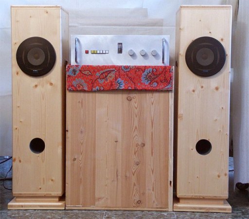
I’ve already commented the performance of French speakers (photo 6) (AudioXpress Dec 2005 Xpress mail), but the results, when driven with this little 10 Watts Matteo, are remarkable. The employment of the tone controls allow to tailor the sound to your pleasure ….. and that is exactly what the reproduced music is meant to be.
I made performance measurement using lower cathode resistor (220 + 50 ohm) with continuous sine wave signal. At 8 W, 1Khz, THD is well below 1% while the HP 3585A spectrum analyser, shows a rapid monotonic decrease of harmonic. Below 100Hz distortion increases slightly…
Under reduced load conditions, overall performance should be even better.
Try it you’ll like it.
|
Performance measurements Test set |
|
|
HP 654/A test oscillator |
(for bandwidth measurement) |
|
Hand made low distortion audio oscillator |
(for distortion measurement) |
|
Hp 331/A distortion analyser |
(for distortion measurement -TDH-) |
|
HP 3585A spectrum analyser |
(for distortion and harmonic analysis) |
|
Tektronix 2225 oscilloscope |
(for signal monitoring) |
|
HP 350D attenuator set |
(for gain and F/B measurement) |
|
HP 403B and Fluke 8050 A voltmeters |
(Voltages monitor) |
Atto Rinaldo Tambre, Italy
|
Photos
|
|
|
Overall view of the amplifier with top cover removed, prior to engraving the front panel
|
|
|
The back panel with all the inputs and outputs terminals, power plug and speakers output.
|
|
|
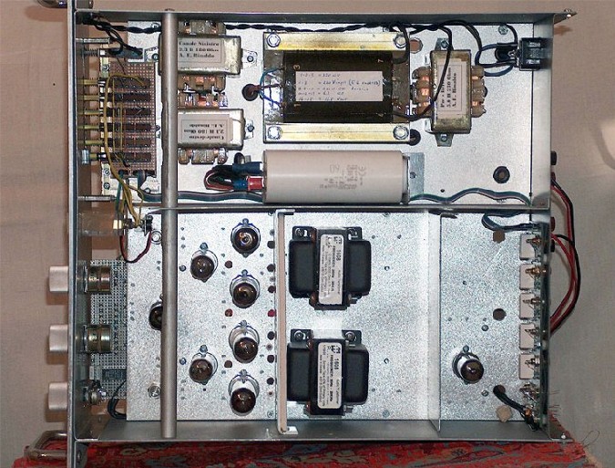
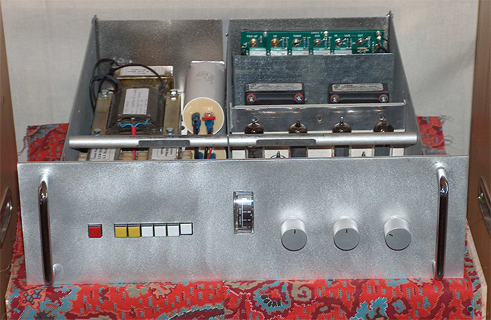
Top view. The power supply section, shows the oversized power transformer, the three chokes and paper/oil filter capacitors. Below, the tubes layout, the relay board at the back end and all the controls in the front panel.
|
|
|
Close-up view of the amplifier wiring.
|
|
|
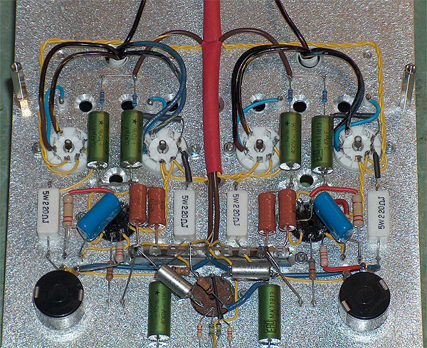
Bottom view of the two sections. On the top the power supply section and, at the bottom, the point to point wiring of the entire amplifier
|
|
|
Matteo, driving the small French speakers while still in my lab.
|
|
About the Author (www.nuvistor.it)
Atto Rinaldo is an active retiree after being employed at IBM for 32 years. He experienced various managerial job responsibilities In Italy, in US and other parts of the world. He received his Radio techniques diploma 48 years ago when vacuum tubes were the technology. Joining IBM in the mid-60s, he witnessed the phase out of vacuum tube computer production which was replaced by the transistors and integrated circuit technology. He enjoys getting back to playing with tubes again.
* Matteo, my beautiful nephew